Shift Registers
To get around the limitations of the Magnolia's 6 IO pins, this lesson will show how to use shift registers to turn three pins into eight. This can be extended to many more outputs with chainable shift registers.
The shift register we are going to use is called the HC595, and the one in your kit is specifically an SN74HC595 (normal one with legs so you can stick it in the prototyping board.)
Qb  1   U   16 Vcc
Qc  2       15 Qa
Qd  3       14 SER
Qe  4       13 OE(ground to enable)
Qf  5       12 RCLK
Qg  6       11 SRCLK
Qh  7       10 SRCLR(power to disable)
GND 8        9 Qh'
The code
The HC595 has a 16 pins, 8 are outputs, the rest are VCC, GND, or other IO pins to control the chip. We will be using all eight output pins that are meant to be the parallel output to power our LEDs. To drive those outputs we will be connecting to the data and clock line for the internal registers, and pushing the internal registers to the output pins with the register clock. We're going to be hard wiring the enable and clear pins and not using the chaining pin to start with.
To start with, let's declare our pins:
int SER = A0;
int SRCLK = A1;
int RCLK = A2;
When using chips with clock lines, we usually find they are triggered by positive-edge. This means the line transitions from a LOW to a HIGH. We'll start by adding this function to the top of our sketch so the main code can call it.
void trigger( int pin )
{
    // assume pin in low state
    // trigger the pos-edge
    digitalWrite(pin,HIGH);
    // reset to low
    digitalWrite(pin,LOW);
}
Inside the HC595, there are internal registers that can either be set high, or low. The internal registers ar called Qa' through Qh'. The external registers are called Qa through Qh. Notice the subtle name difference. When RCLK is triggered, the values of the external registers are overwritten by the internal ones. This means we can safely modify the values on the internal registers without worrying that anything is visible outside.
To modify the internal registers, we need to use SER and SRCLK. Every time the SRCLK is triggered, two things happen: The values in Qh' down to Qb' get overwritten by Qg' down to Qa', and then the value of SER is read, shunted into Qa'. This is why it is called a shift register. Every time you trigger SRCLK all the values are shifted along to the next Q' register.
To shift out all eight values, first we need a function to push one value out.
void put_one( int val )
{
    // set SER
    digitalWrite(SER, val);

    // trigger a shift
    trigger(SRCLK);
}
This sets the SER line, then triggers the SRCLK, meaning the values get shifted. At this point, the outputs Qa - Qh are still in whatever state they were in before, but Qa' - Qh' have been shifted, or updated.
Often we will use binary to feed into shift registers, so we will do that and write a function to take a byte (8 bits) and set all the shift register values in sequence, then trigger RCLK to update the Q registers (the external ones.)
void send_out( int bits )
{
    for( int i = 0; i < 8; ++i )
    {
        // send only the lowest bit
        put_one( bits & 1 );

        // move the next highest bit down
        bits >>= 1;
    }
    trigger(RCLK); // move Q' into Q
}
This function can now be used by our main loop and setup code.
void setup()
{
    pinMode(SER, OUTPUT);
    pinMode(SRCLK, OUTPUT);
    pinMode(RCLK, OUTPUT);
}

int t;

void loop()
{
    send_out( 1 << (t&7) );
    delay(125);
}
This sketch, once we have wired up the lesson, should have a row of lights fire in sequence once per second.
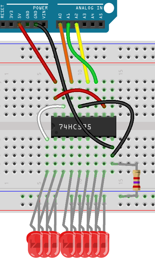
Wiring
Because there are five wires from the Magnolia to the board, two of which are basic lines, w're going to start with some prototyping tips.
First, assume that we're going to take a lead from GND and VCC and drive the power rails on your prototyping board.
Any time the wiring requires a line from VCC or GND now, take it from these powered rails.
Place your shift register with the little dimple near the top, but a few rows down. Just so you have a little bit of space to work with. The top right pin (next to dimple) needs connecting to VCC, and the bottom left needs connecting to GND.
To hard wire the chip as enabled, wire GND to pin 13 (three down from VCC). To stop the chip from self clearing, power SRCLR with VCC. SRCLR is pin 10, one up from bottom right.
Take three long leads and connect SER (pin 14) to A0, SRCLK (pin 11) to A1, and RCLK (pin 12) to A2.
Take a jumper and jump between Qa (pin 15), and the row above Qb. This is so you can have all your LEDs plugged straight into the 8 rows starting above Qb.
Insert all your LEDs anode by the chip. All the cathodes should link to one of the two remaining rails. This rail will have a 2k7 resistor just to make sure the overall current drop doesn't drain the Magnolia. The 2k7 resistor should then be linked to GND.
Upload!
More outputs
Pin 9 is high when Qh' is high. This means that if there are two chips, then chip 1 Qh' can be attached to chip 2 SER, The SRCLK and RCLK can be wired common, then you have a 16bit shift-register. This sequence of adding more chips eventually runs out of juice, but not so quickly that it matters for most hobby projects.